


THE REQUEST
We were going to order some automatic transfer switches (ATS) than I noticed the PDUs with integrated ATS. Would providing power to the uplinks via two different APC UPS units. Would this satisfy
THE RESPONSE
Providing two different UPS does not mean they will be phase synchronized.
A test of the synchronization will be needed. As a Server Technology engineer stated:
Phase synchronization of the sources is required. The two AC sources MUST be the same frequency and the Voltage potential difference of the two sources should never be greater than 30 Volts.
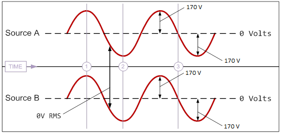
If each source is a North American 120 VAC single-phase with one ‘hot’ line and a neutral, the waveform of the ‘hot’ line for source A must directly and continuously match the waveform of source B throughout the constant of time. Above is an illustration showing the waveform of two 120V single-phase sources that are synchronized.
- At time point #1 both sources are at peak forward voltage. At time point #2 both sources are at peak reverse voltage. At time point #3 both sources are at zero volts. The waveform for both cycles match at any point in time.
- With the two sources perfectly synchronized as illustrated above, a simple volt meter measuring the potential between the ‘hot’ line for source A and the ‘hot’ line for source B will show zero (0) volts at any point in time.
ADDITIONAL NOTES:
- If both UPS1 and UPS2 are the same type and include the necessary technology to share oscillator information for their DC-to-AC inverters, the two UPS should be able to synchronize their respective outputs. Check with the manufacturer of the two UPS units if you are unsure as to whether or not they provide synchronization technology.
- Regarding tolerance, the two phases do not need to be perfectly synchronized. They do, however, need to be matched close enough that there is never greater than a maximum potential of 30 volts. After first using a volt meter to measure potential between the hot phase of source A and the hot phase of source B, you should only connect the FSTS if potential between the two phases is equal to or less than 30 volts (≤30V).
Checking for Phase Sync
between two C19 connectors, 208V Nominal
- Set the volt meter to measure AC voltage up to at least 300V.
- Measure voltage between Line (L) and Ground (G) on the C19 end of the power cord attached to the “A” source.
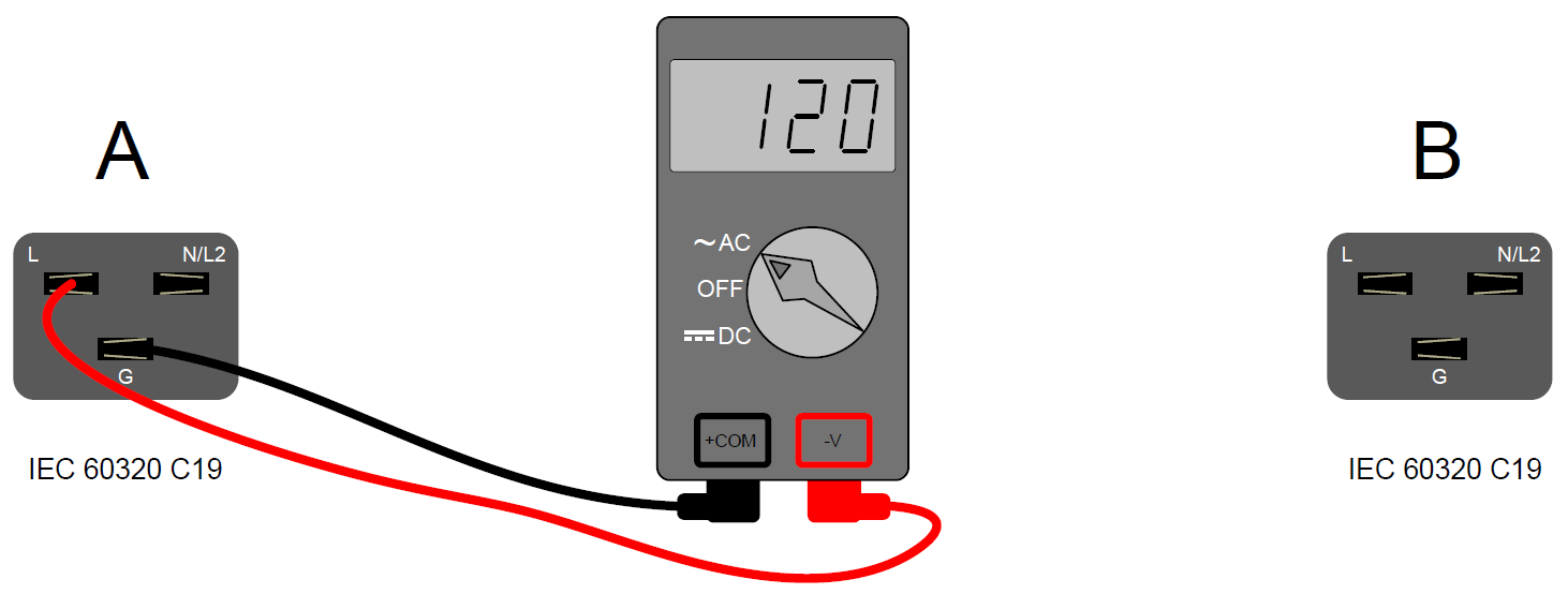
Phase Sync Step 2: The reading should be approximately 120V. - Measure voltage between Ground (G) and Line 2 (N/L2) on the C19 end of the power cord attached to the “A” source.

Phase Sync Step 3: The reading should be approximately 120V. - Measure voltage between Line (L) and Line 2 (N/L2) on the C19 end of the power cord attached to the “A” source.
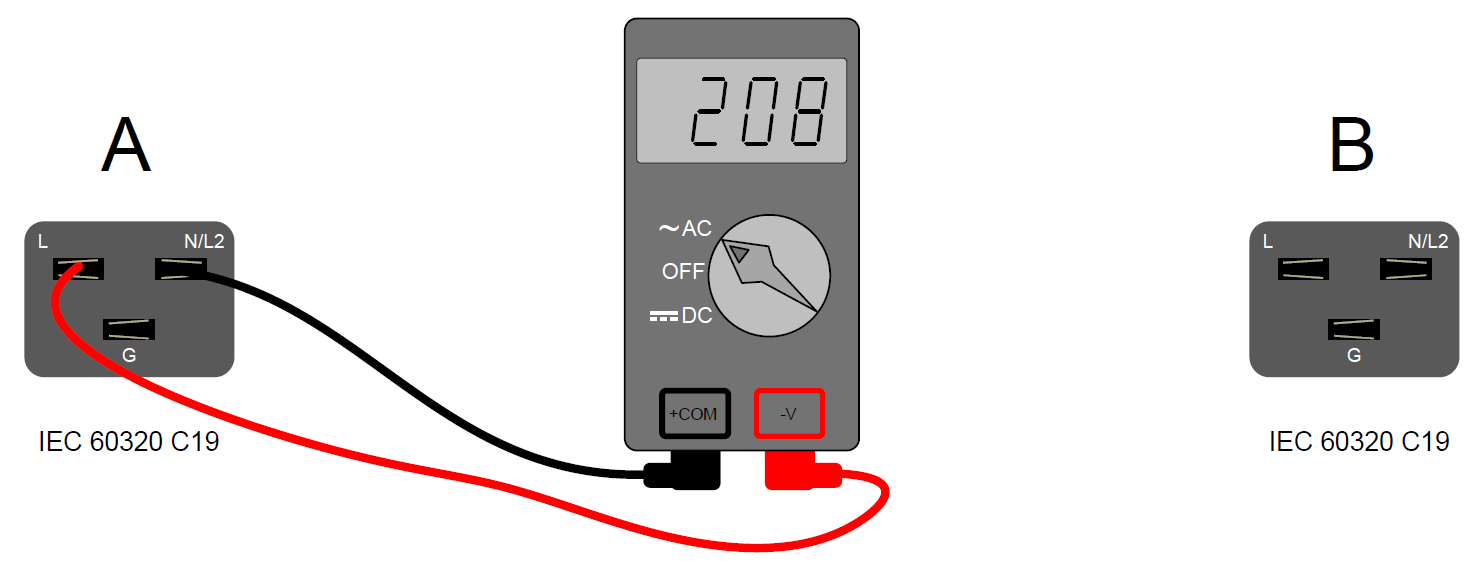
Phase Sync Step 4: The reading should be approximately 208V. - Measure voltage between Line (L) and Ground (G) on the C19 end of the power cord attached to the “B” source.
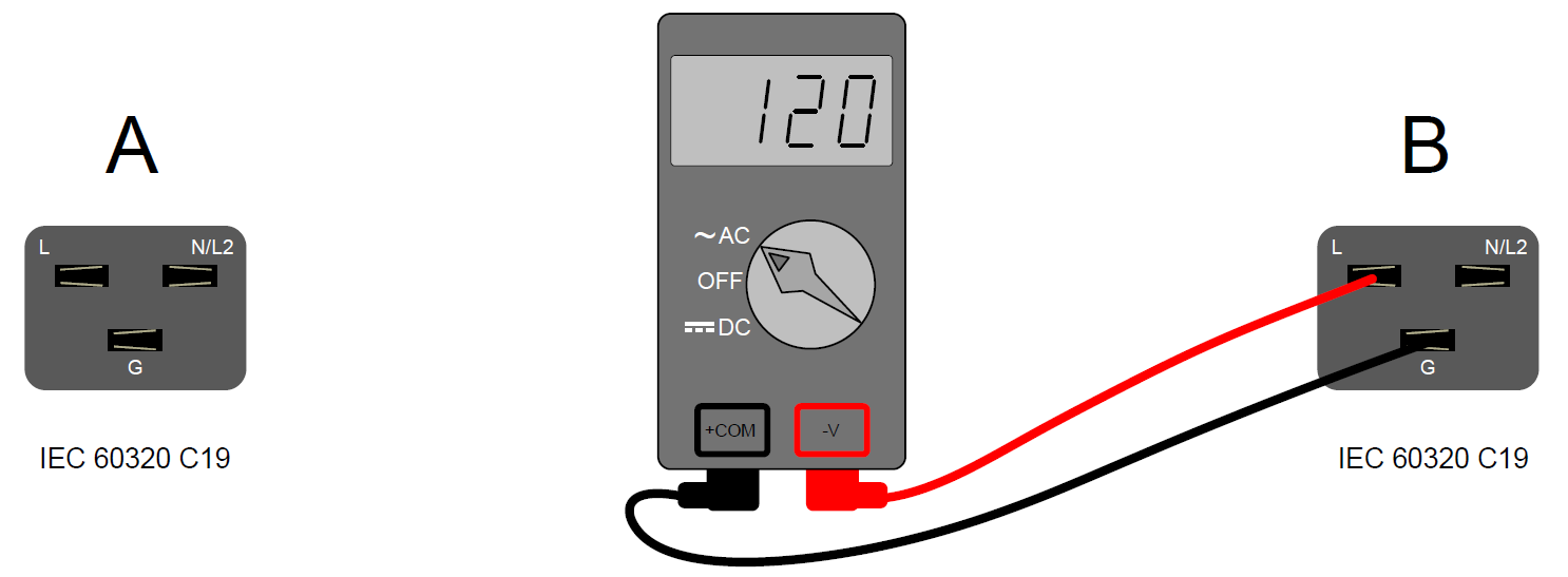
Phase Sync Step 5: The reading should be approximately 120V.
- Measure voltage between Ground (G) and Line 2 (N/L2) on the C19 end of the power cord attached to the “B” source.
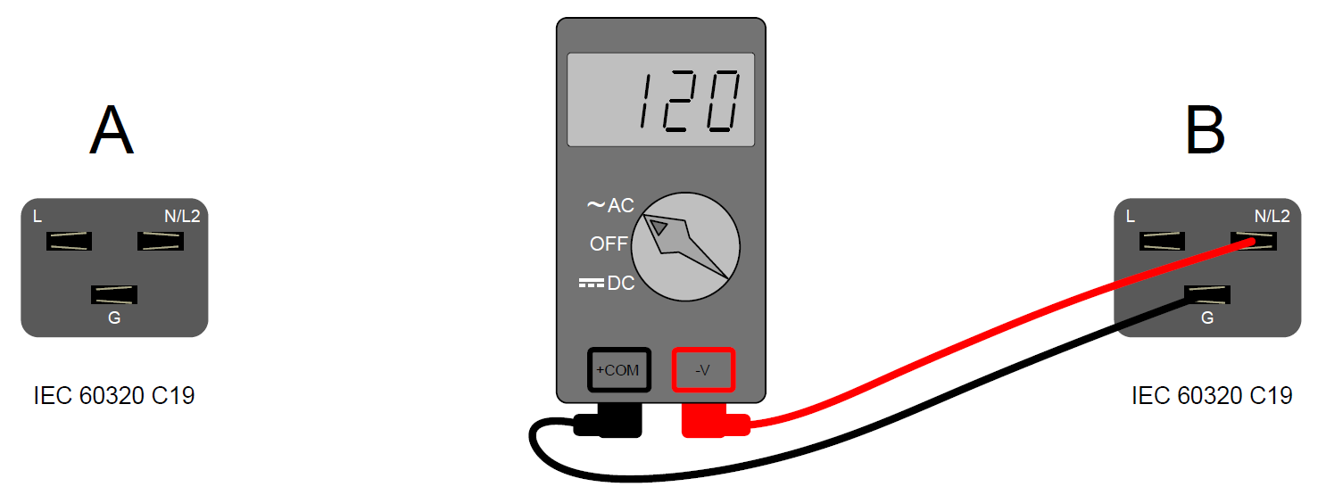
Phase Sync Step 6: The reading should be approximately 120V.
- Measure voltage between Line (L) and Line 2 (N/L2) on the C19 end of the power cord attached to the “B” source.
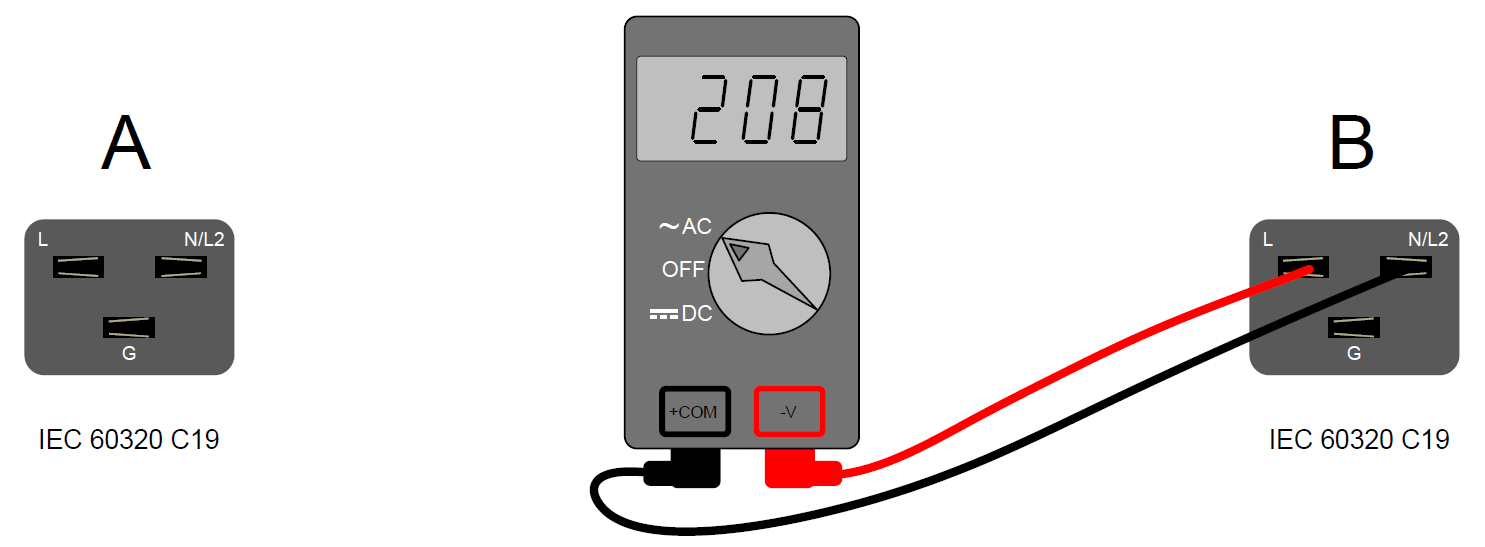
Phase Sync Step 7: The reading should be approximately 208V.
- Measure voltage between Line (L) on the “A” source and Line (L) on the “B” source.
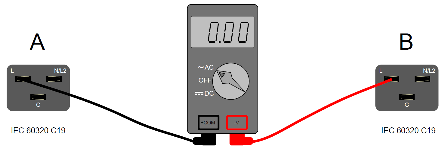
Phase Sync Step 8: The reading should be at or near zero (0) volts if the previous readings were correct and the two Lines are synchronized. - Measure voltage between Line 2 (N/L2) on the “A” source and Line 2 (N/L2) on the “B” source.
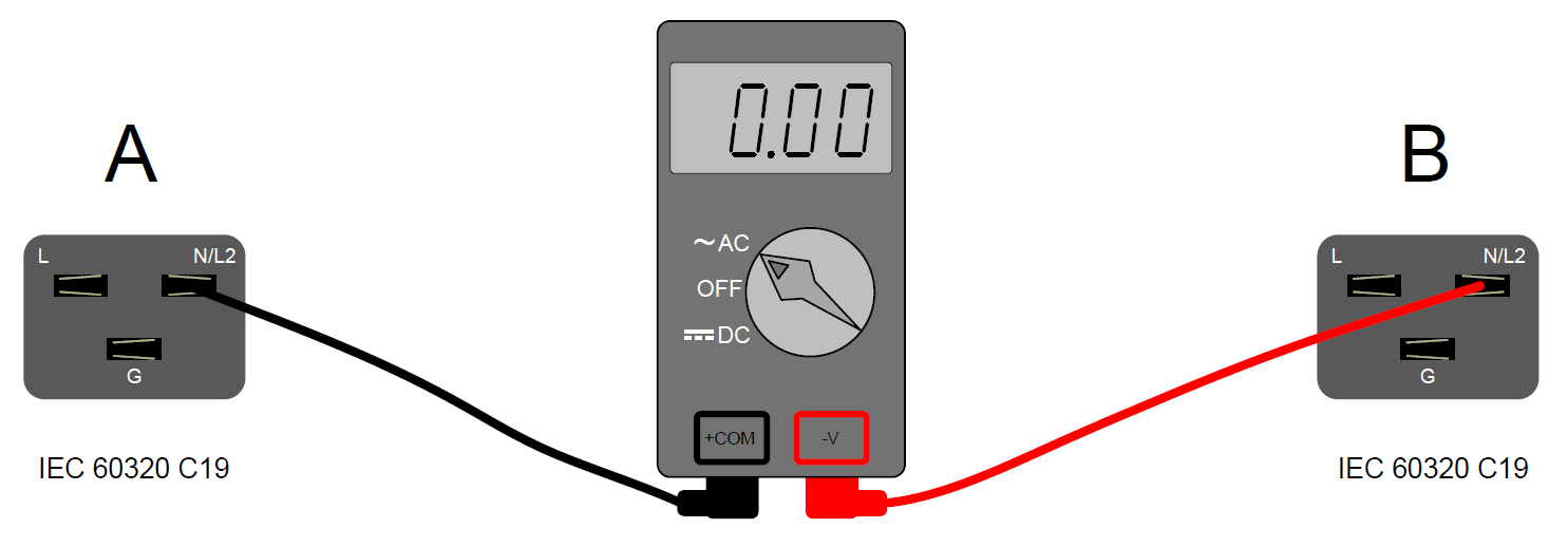
Phase Sync Step 9: The reading should be at or near zero (0) volts if the previous readings were correct and the two Lines are synchronized.
Special thanks to our friends at
![]()